
Understanding Front Panel Connectors in a PC Build
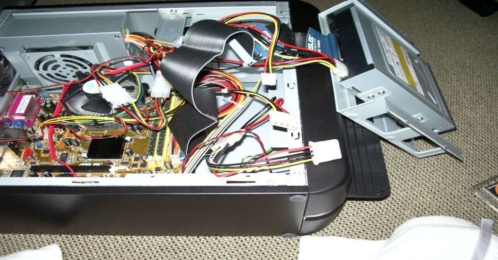
When assembling or troubleshooting a PC, one of the critical aspects is correctly connecting the front panel connectors to the motherboard. These small cables control essential functions like the power button, reset button, power LED, and HDD activity light.
🔹 Identifying Front Panel Connectors
The front panel cables typically include:
✔ Power Switch (PWR SW) – Turns the system on and off.
✔ Reset Switch (RST SW) – Allows a system reset.
✔ Power LED (PWR LED) – Indicates when the system is powered.
✔ HDD LED – Blinks when the hard drive is active.
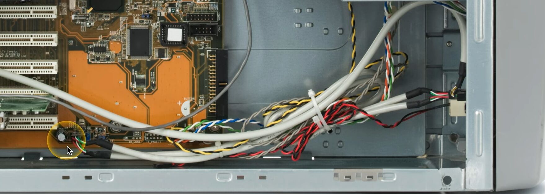
✔ Speaker/Buzzer – Emits beep codes for diagnostic purposes.
🔹 Connecting to the Motherboard
1️⃣ Locate the F_PANEL or Front Panel Header on the motherboard.
2️⃣ Refer to the motherboard manual for the correct pin layout.
3️⃣ Match the positive (+) and negative (-) leads for LEDs to avoid polarity issues.
4️⃣ Gently insert each connector onto the corresponding pins.
🔹 Common Issues and Troubleshooting
- PC won’t turn on? Check if the power switch connector is securely attached.
- No LED indicators? Verify the polarity of the LED connections.
- No response from buttons? Ensure the cables are properly seated on the header.
Proper installation of front panel connectors ensures seamless power control, status indication, and diagnostics for your system.
Find more tech insights on Matching Tips.
#PCBuilding #MotherboardConnections #FrontPanelSetup

Leave a comment